For the operation of sizing a set of back beam containing predetermined number of end to be sized, is a in stand, made of cast iron frame work called the “creel” in the conventional sizing machine back beams of about 500mm flange. With the present trend of mass production to improve the efficiency of the operation and consequent large package beam flange of about 750mm are quite common and accordingly either new type of creel have been designed or old creels have been to suit the new requirement.
There are mainly three type of sizing creel are used.
- Over-under creel or staggering creel or zigzag creels
- Vertical creel
- Inclined creel
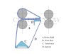
Over-under Creel
This creel called zigzag creel because of the serpentine path of the yarn that passes over the surface of the beams on the top layer of the creel and then passes under the beam s in the bottom layer of the creel. Each back beam is supported in the creel, the beam spindle of which rest in the adjustable bearing of arrangement the bearing have a provision so that they can be moved inward-toward the center of the creel or outward by simple turning a hand wheel connected to as threaded spindle.

The number of beams required for a particular set depends on the number of ends in resultant fabric and the warping creel capacity for example, if the total number of end in fabric is 3360 and the warping creel capacity is 600 ends, then 6 warper’s beams each with 560 end are require for thus particular set to be sized, with width weaving machine like the size, where even two or three fabric of smaller width can be simultaneously woven on the same machine , the total number of end in the sized beam will increase two or three fold and in such cases it is not uncommon to have about 12 to 16 beam in the creel for general type of weaving normally 6 to 8 back beam are placed in the creel from a set of say 6 back beam. The threads are withdrawn from the top side of the rear most beam in the top raw and passed under guide. The second where they unite with drawn thread that are withdrawn from the bottom side of the beam and so on until all the thread are gathered into one sheet of warp thread that passes over a guide roller when they are in the near size paste in the size box.
Merits
of over under Creel
- Loading and unloading of beam is easy
- Supervision of warper’s beam during unwinding is easy
-
During
unwinding the warp sheet comes under immense stretch.
- This happens due to the warp sheet passing around the subsequent beams in order to drive them.
- Difficulties in locating and cutting lappers
- The back beams should be kept perfectly parallel to the size and squeeze roller nip.
- The beams should be aligned in such a manner that the selvedge ends will not chafe by rubbing against the cast iron flange of any of the beam ahead of the beam from which the ends have emerged.
- The beam flange should be straight as many times dye to the bad material handling and storing practices the flange are bent.
- The beams should rotate freely in the bearing as otherwise the yarn will be stretched on the beam which is not moving freely and this will cause more apparent length of the warp being pulled out form such a beam than the other beams which are rotating freely which is resulted in unsized hard waste and its left on the beam which the other beams have exhausted.
- Lateral setting of beam sides way setting
- Height setting of beam
- Height setting of creel


0 Comments